
Negative Resistance
This tutorial is going to cover the topic of negative resistance. At first, it might seem like a strange idea that you could have a current flowing in the opposite direction of an applied voltage; but, hopefully by the end of this tutorial you will have a better intuitive understanding of what a negative resistance really is, and how to build a negative resistor out of common circuit components.
- What is a Negative Resistance?
- Creating a Negative Resistor Using a CCVS
- Creating a Negative Resistor Using a VCVS
- Creating a Negative Resistor Using Real Components
- Example Problem
- Summary
What is a Negative Resistance?
Our first step is to try to develop an intuitive notion of what a negative resistance is, and how it would behave in a circuit. The definition of resistance is governed by simple a relationship called Ohm’s Law.
$$R=\frac{V}{I}$$
We can see by looking at this equation, that to create a negative resistance we would need to create a circuit component which develops a negative voltage whenever a positive current is passed through it (assuming passive sign convention). However, rather than thinking about it in terms of mathematics, a simpler way to understand the idea of negative resistance is to consider the resistance of two resistors in series.
From a basic understanding of circuits, we know that the values of resistors add in series. Therefore, if we had a resistor with a positive value of 11 Ohms in series with a resistor with a negative value of -4 Ohms, the equivalent resistance in series comes out to 11 + (-4) = 7 Ohms. In other words, we can think of a negative resistor as a device we can put in series with another resistor to decrease its value.
Creating a Negative Resistor Using a CCVS
Now that we have an idea of what we are trying to achieve, we can start our quest to create a negative resistor returning to Ohm’s Law and rearranging.
$$R=\frac{V}{I} \Rightarrow V=RI$$
Looking at this equation, we notice that it looks very similar to the equation governing the operation of a current-controlled voltage source (CCVS). In the equation below, $V_{CCVS}$ is the voltage output of the CCVS, $I_c$ is the controlling current, and $r_c$ is the “gain parameter” with units of Ohms—hint, hint!
$$V_{CCVS}=r_c I_c$$
If we make the assumption that the control current $( I_c )$ is flowing into the positive terminal of the CCVS, we can easily calculate the resistance $( R_{CCVS} )$ of the CCVS by once again using Ohm’s Law.
$$R_{CCVS}=\frac{V_{CCVS}}{I_c} = R_c$$
This leads us to the solution that the resistance of a current-controlled voltage source, whose control current is measured at the positive terminal, is simply equal to the gain parameter $( r_c )$ of the CCVS. By utilizing this fact, we can easily create a negative resistor simply by using a CCVS with a negative gain parameter. An example of this method can be seen in the figure below. Here we implement a resistance of -4 Ohms using the CCVS method.

Creating a Negative Resistor Using a VCVS
At this point, some readers might be wondering “why go any further?” Unfortunately, a current-controlled voltage source isn’t a very practical real world circuit component. In fact, many circuit simulation programs (such as LTspice) don’t even include CCVS models! We can, however, overcome this limitation by using a component which is more readily at our disposal: a voltage-controlled voltage source (VCVS).
By looking at the equation governing the operation of a VCVS, we can see that it looks identical to the equation of a voltage amplifier. In the equation below, $V_{out}$ is the voltage output of the VCVS, $V_{sense}$ is the controlling voltage (i.e., the input voltage to an amplifier), and $G$ is the gain parameter (which is a unitless ratio).
$$V_{out}=G V_{sense}$$
With the help of Ohm’s Law (last time, I promise!), we find that we can make the VCVS mimic a CCVS through the use of a sensing resistor $( R_{sense} )$ in series with the VCVS to measure current. The current flowing through $R_{sense}$ will create a voltage which is proportional to the current, and can then be picked up by $V_{sense}$. The proposed setup can be seen in the figure below.
While the above setup gives us a structure that can be used to create a negative resistor, we continue our analysis by developing a set of analytical equations describing this circuit’s operation. The voltage developed across the sense resistor is written below.
$$V_{sense} = I_{sense} R_{sense}$$
We can now take the equation governing the VCVS, make the following substitutions and regroupings, and make the equation look like the equation governing the CCVS.
$$V_{out}=G V_{sense} = G (I_{sense} R_{sense}) = (G R_{sense}) I_{sense}$$
Here we see that $(G R_{sense})$ takes the place of $r_c$ from the CCVS equation. Also, we know from the previous section that $r_c$ is the resistance of the CCVS negative resistor circuit. However, to find the total resistance $R_{total}$ of VCVS circuit we are building, we need to take into account the added resistance of the current sensing resistor $(R_{sense})$.
$$R_{total} = R_{sense}+r_c$$
Making the substitution $r_c = (G R_{sense})$, we obtain:
$$R_{total}= R_{sense}+G R_{sense} = R_{sense}(1+G)$$
From this equation, we can solve for the gain parameter of the VCVS that we would need to create any desired resistance in our circuit.
$$G = \frac{R_{total}}{R_{sense}} – 1$$
Using the set of equations we have developed, we now have the tools to create a negative resistor of any value by using only a VCVS along with a sensing resistor. As an example, we now create a negative resistor with a value of -4 Ohms. By arbitrarily choosing $R_{sense} = 2 \: Ohms$, we can calculate the required gain parameter of the VCVS by using the previous equation.
$$G= \frac{R_{total}}{R_{sense}} – 1 = \frac{-4}{2} – 1 = -3$$
The completed example circuit can be seen below.
Creating a Negative Resistor Using Real Components
Now that we have created a theoretical circuit describing a negative resistor, our final step is to create a practical implementation using real world components. To reiterate from the previous section, a VCVS is nothing more than a voltage amplifier with differential input and differential output. To simplify the circuit design, we will make the assumption that one of the terminals of our negative resistor will always be connected to ground. This assumption allows us to use a voltage amplifier which has differential inputs, but only a single ended output. I’ve attached a schematic for an inverting amplifier like this as a reference in the figure below.

The gain of this amplifier is set by the ratio of resistors $R_f$ and $R_1$.
$$G=-\frac{R_f}{R_1}$$
Therefore the input-output relationship of this amplifier is governed by the following equation.
$$V_{out}=-\frac{R_f}{R_1}(V_{in+}-V_{in-})$$
The similarity to the equation governing the VCVS $(V_{out}=G V_{sense})$ is easy to see if we make the following substitutions.
$$G = -\frac{R_f}{R_1}$$
$$V_{sense} = V_{in+}-V_{in-}$$
This allows us to directly substitute for the VCVS in the negative resistor circuit with our differential amplifier circuit. We can solve for the required ratio of $R_f$ to $R_1$ by using the equation used to calculate the required gain of the VCVS in the previous section. The equation is repeated below.
$$G=\frac{R_{total}}{R_{sense}} – 1$$
$$-\frac{R_f}{R_1}=\frac{R_{total}}{R_{sense}} – 1$$
$$\frac{R_f}{R_1}=-\left( \frac{R_{total}}{R_{sense}} – 1 \right)$$
By directly replacing the VCVS from the previous section with the circuit above, we obtain the final schematic for the negative resistor seen below.
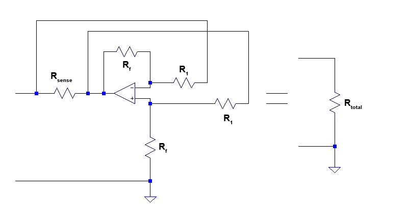
We find the overall resistance of the circuit by substituting the gain equation of the differential amplifier circuit into the equation for calculating $R_{total}$ of the VCVS circuit developed in previous section.
$$R_{total} = R_{sense}(1+G) = R_{sense}\left(1+ -\frac{R_f}{R_1} \right) $$
Example Problem
To make sure that everything discussed is correct and checks out, we will work out a single example problem and simulate it.
Example: Create a negative resistor with a value of -4 Ohms. Use $R_{sense}=2\: Ohms$, and keep both $10\: kOhms \leq R_1 \leq 1\: kOhms$ and $10\: kOhms \leq R_f \leq 1\: kOhms$. Using Spice, calculate the equivalent series resistance of the negative resistor in series with an 11 Ohm resistor, using a 5 V DC voltage source as the test voltage. The total equivalent resistance should be equal to 11 – 4 = 7 Ohms.
We start by calculating the required gain of the amplifier.
$$G = \frac{R_{total}}{R_{sense}} – 1$$
$$G = \frac{-4}{2} – 1 = -3$$
Now that we know the gain, we can calculate the values of $R_1$ and $R_f$ to set the gain of the differential amplifier circuit. To make our calculations easy, we will choose $R_1 = 10\: kOhms$.
$$G=-\frac{R_f}{R_1}$$
$$-3=-\frac{R_f}{10,000}$$
$$ R_f = 3 \times 10,000 = 30,000\: Ohms$$
Now that we have the values of all the components, we can plug them into our circuit. Here is what we get!
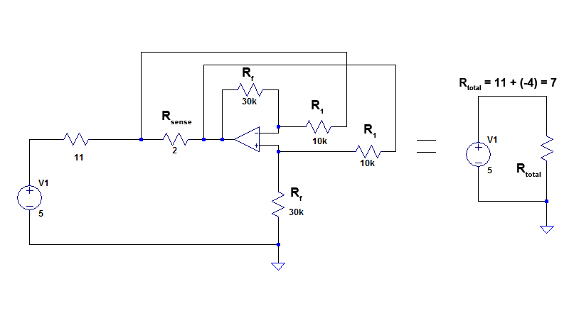
To verify our results, we run the simulation and everything checks out. Because the differential amplifier has a finite input resistance, this will slightly affect the operation of our circuit. We can take this into account while we are designing our circuit; but, I will leave that as an exercise for the reader (don’t you always love it when textbooks do that).
Summary
As a summary, I will outline our thought process, the steps we took, and the final result so that we can collect our thoughts.
- We notice that a current-controlled voltage source has a similar equation to a resistor.
- We realize that we can create any value of resistor (both positive and negative) if we use the current flowing into the positive terminal of the CCVS as the sensing current, and choose a suitable gain parameter value.
- We can mimic the CCVS using a voltage-controlled voltage source if we use a current sensing resistor.
- We can implement a VCVS by using a differential amplifier.
- By substituting the VCVS for the differential amplifier, we obtain a practical method to implement a negative resistor.
The negative resistor circuit can be seen below
The resistance of the circuit is given by the following equation.
$$R_{total} = R_{sense}\left( 1-\frac{R_f}{R_1} \right) $$
ROBERT Bruno
HI, Thank you for your work. Have you achieved a "living" negative resitance system under LtSpice ? Thanks for your answer. Best